gbaHD Upcycle Shield DIY kit install guide
This guide will help you with the assembly of the gbaHD Upcycle Shield. Be aware that this assembly is a rather difficult and requires a good amount of soldering experience.
Parts needed:
- gbaHD Upcycle Shield Kit
- GBA donor board
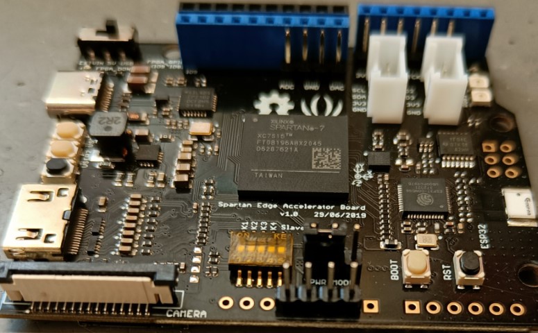
- Spartan Edge Accelerator including supplied female header pins.
- Micro SD Card
Step 1
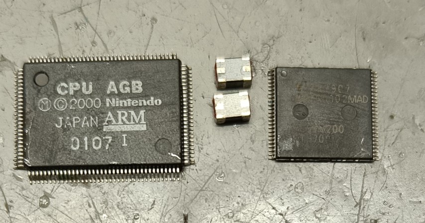
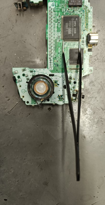
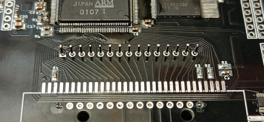
First remove the CPU, RAM and EMI Filters from your Donor board. We recommend using a GBA, that is completely broken to harvest the parts from. For the removal we recommend using a hot-air desoldering tool. We set our heatgun to 350℃ and preapply some flux. Using some fine pliers you can put a bit of pressure on the chip, so it will lift itself as soon as the hot air melts the solder.
Step 2
Now flash the Spartan Edge Board according to the wiki https://github.com/gbaHD/GBAHD-Shield/wiki/Setup-Guide-Spartan-Edge-Acceelerator-Board#chrome-based-browser-setup
Add a jumper to the spartan edge and swap the power mode https://github.com/gbaHD/GBAHD-Shield/wiki/Setup-Guide-Spartan-Edge-Acceelerator-Board#preparing-the-spartan-edge-board
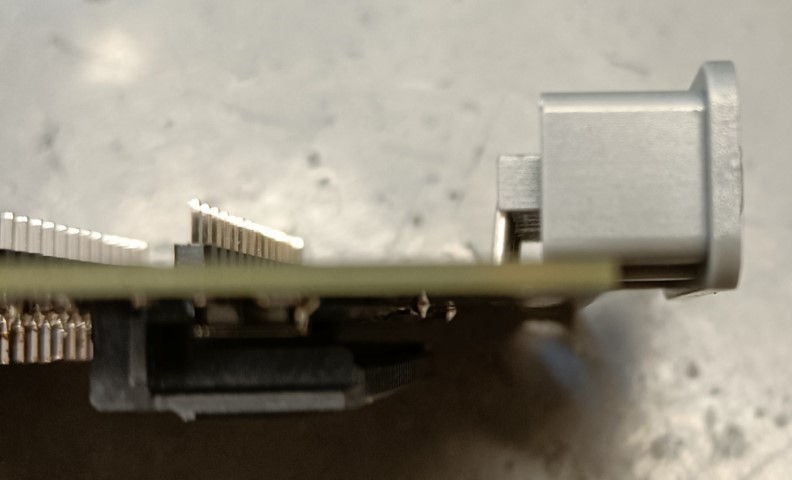
Remove the power switch from the spartan edge board as we will replace it with our overvolt protected version.
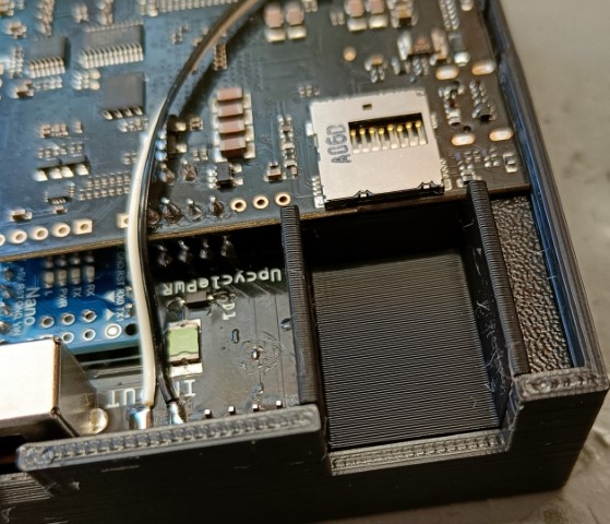
Setup your micro SD card https://github.com/gbaHD/GBAHD-Shield/wiki/Setup-Guide-Spartan-Edge-Acceelerator-Board#preparing-the-sd-card
Step 3
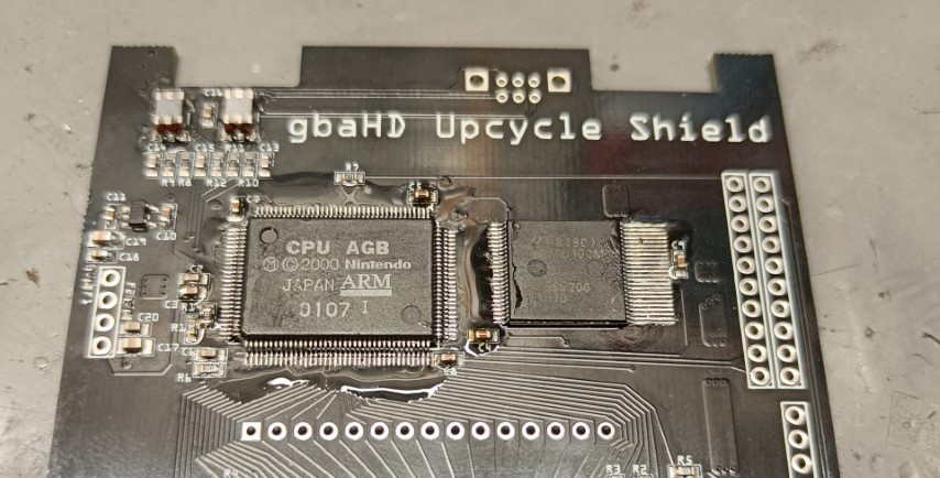
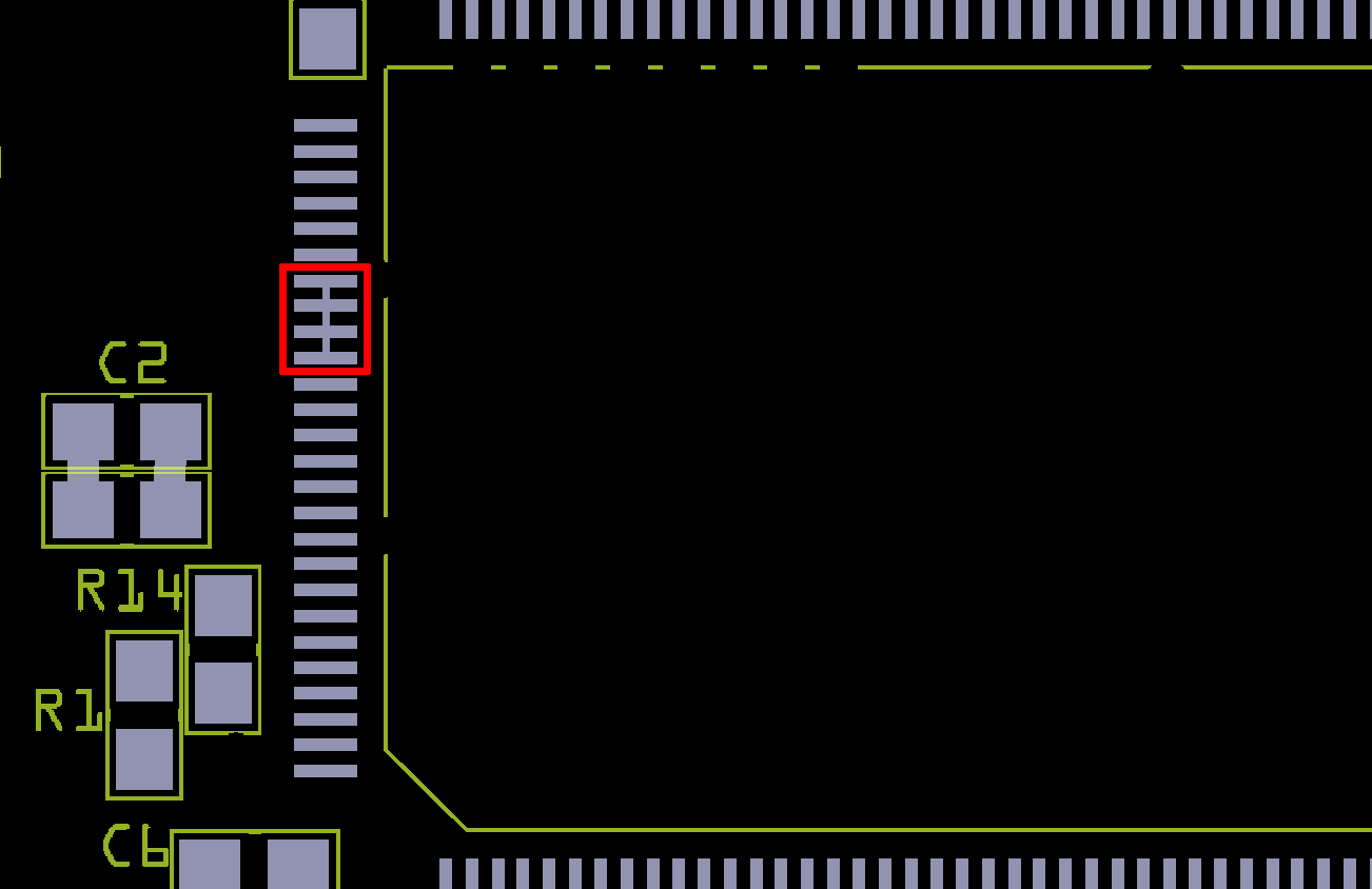
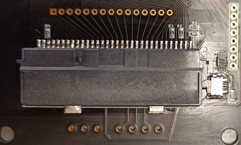
Solder the harvested parts onto the Upcycle pcb. Make sure to use enough flux and verify that the pins are not bridged. 4 pins, marked in red, on the left side might bridge due to being connected to eachother.
Step 4
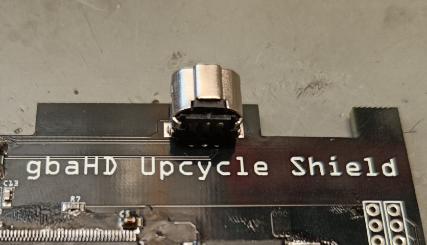
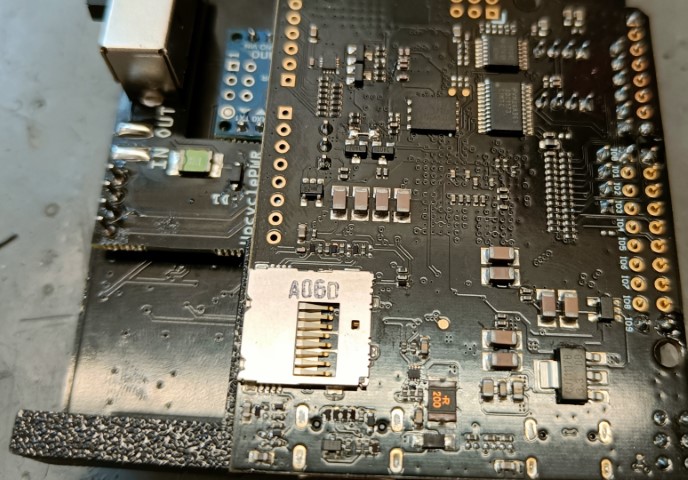
Solder in the link port
Step 5
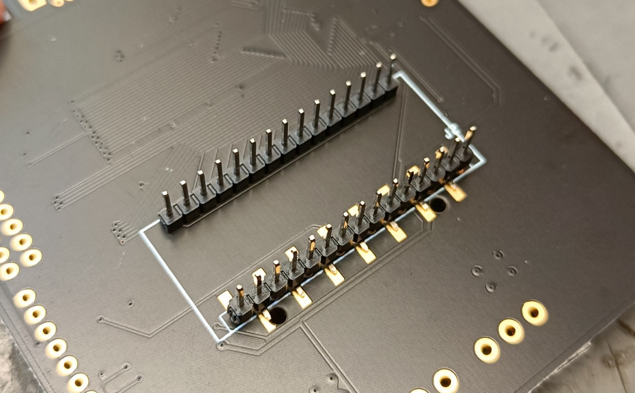
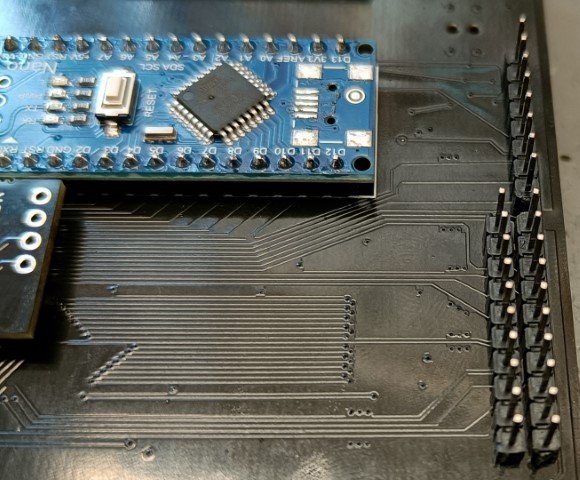
Solder in both 15 pin headers on the top side. Putting the Arduino on the backside and using it for alignment will avoid later troubles. Remove the Arduino again after soldering the headers on the top side.
If you have the V1.1 of the board you do Step 6 first and them proceed here. You can now use the smd header for the pinrow below the cartridge connector.
Step 6
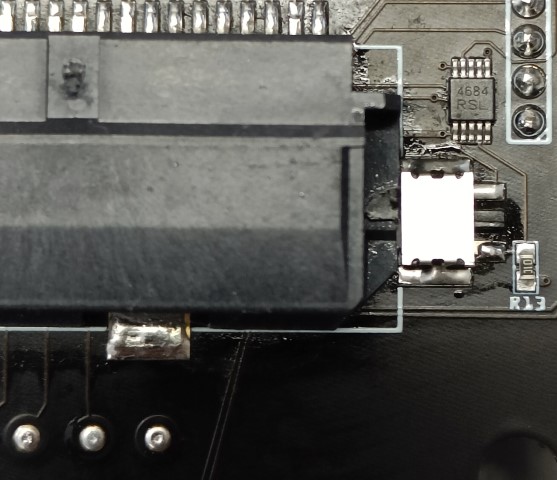
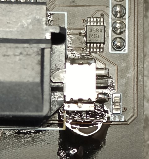
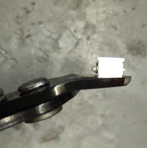
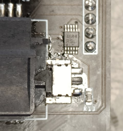
Solder in the cartridge port and micro switch (If your switch has no trimmed shield you can find the guide how to trim it here). Make sue to align both parts before soldering them. After soldering both of them make sure that the switch can be easily triggered. If not you can relieve some tension by applying some heat to the shield pad near the small chip.
Step 7
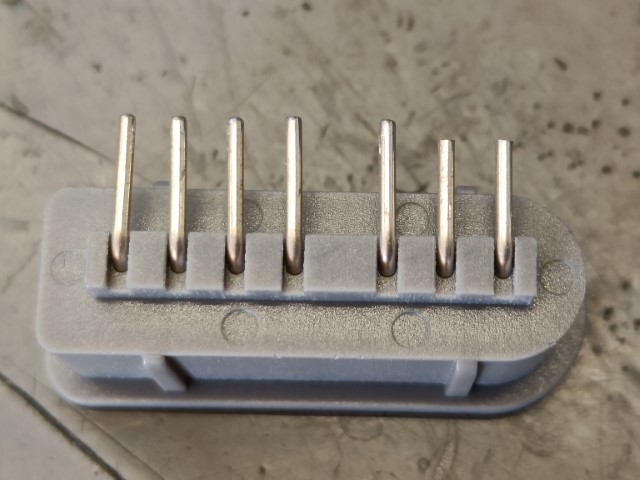
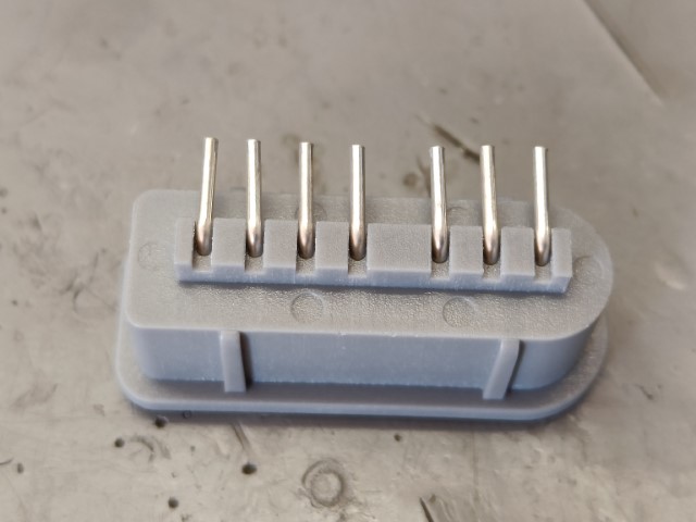
Note: Early kits (Before August 2024) had these legs pretrimmed, if the ends of the legs are flat they have already been trimmed.
Trim the SNES controller ports legs by 1.5-2mm.
Step 8
Solder in the SNES Controller Port and make sure it aligns as seen in the image. Solder has to be applied from the bottom side here.
Step 9
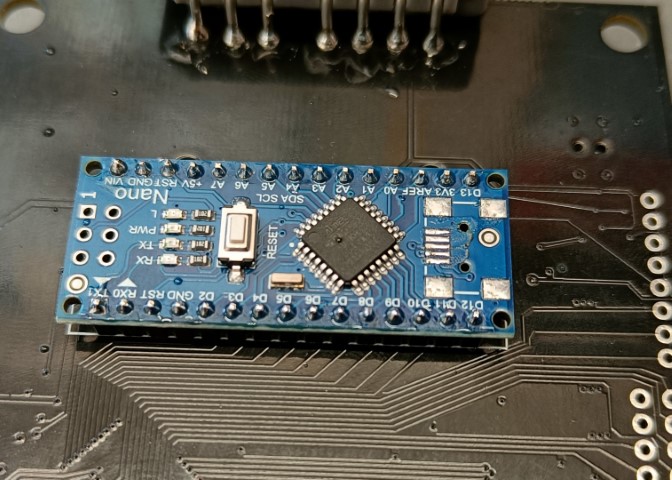
Solder the Arduino Nano
Step 10
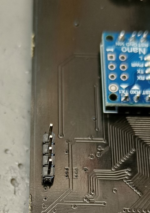
Solder the pin headers for the power switch and mount it in. Push the power switch completely down on the pins and make sure the power pcb floats in an even distance from the mainpcb.
Step 11
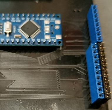
Solder the rest of the headers
Step 12
Mount the female header pins.
Step 13
Solder the spartan onto the headers using the alignment piece and rest the spartan on its fpc-connectors pins. (solder all connections, image shows in progress)
Step 14
Solder the 4 pin header to the Spartans power section
Step 15
Attach the Spartan to the Shield and solder the power connectors. use the alignmentpiece again this time rest the spartanboard on the small pcb part between the fpc connectors pins and pcb edge.
Step 16
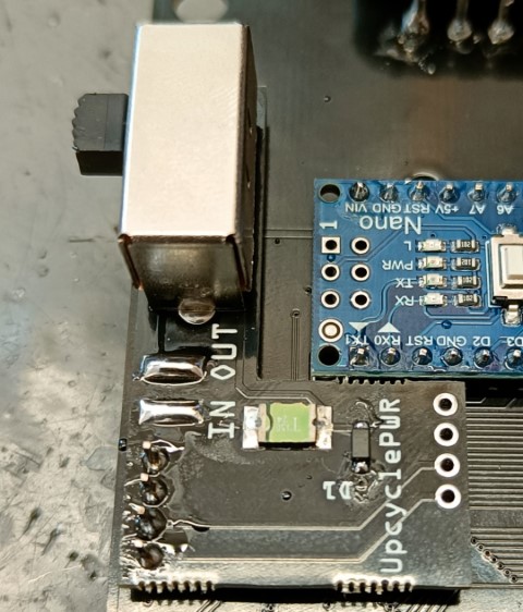
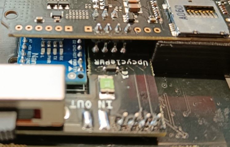
Now connect the cables from the old power switch to our power module, make sure the cables are connects the right way, otherwise the overvolt protection will not work. The center pin of the old switch has to be connected to Out on the UpcyclePWR board.
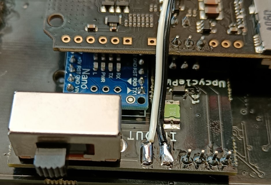
Step 17
The electrical assembly is now finished. You now want to test the whole functionality before finishing the assembly.
Start by testing if there is a short between GND, 3.3V or 5V. If not boot up the gbaHD with no game and check what you get from the Mini HDMI port. You want to see the normal GBA bootscreen. At the same time you want the Arduino L led to light up. If this works, turn the unit off again and turn it on while you trigger the microswitch. If you get a Game Boy bootscreen you are ready to continue.
Now insert a GBA and a Game Boy game and check if both of them work. Add a SNES controller to check if all buttons work.
You can enter the OSD with the combination | UP | R | L | SELECT | and activate the button overlay for an easy way to test all buttons.
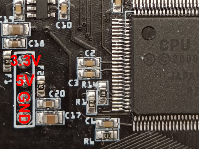
Debuging if 3.3V and 5V are present. Insert a Game Boy game for this debugging guide.
| Issue | Possible fix |
|---|---|
| No Image | Some CPU pins are not soldered propperly. Mostly this means either reset, image or clock pins. Check and reflow Pins on the left and top of the CPU. |
| Nintendo or Black Bar appears but Game Boy is either a color block or missing letters. | Some CPU and / or ram pins are not soldered propperly. Mostly this means either image or ram pins. Check and reflow pins on the top and right of the CPU as well as all ram pins. |
| Nintendo is not showing propperly | Your test game might be dirty, clean it first. Some CPU and or Cartridge Connector pins are not soldered propperly. Check and reflow Pins on the bottom of the CPU as well as the cartidge connector. If this brings no success verify R2 (47 Ohm) R3 (47 Ohm) and R4 (15 Ohm). If all is good but it still fails you might have a rare case of a broken CPU |
| Game Boy works, GBA freezes after Bootscreen | Some CPU and / or ram pins are not soldered propperly. Mostly this means either image or ram pins. Check and reflow pins on the top and right of the CPU as well as all ram pins. |
| GBA Cartridge reports corupted savefile | R2 has failed and needs to be replaced with a 47 Ohm resistor. |
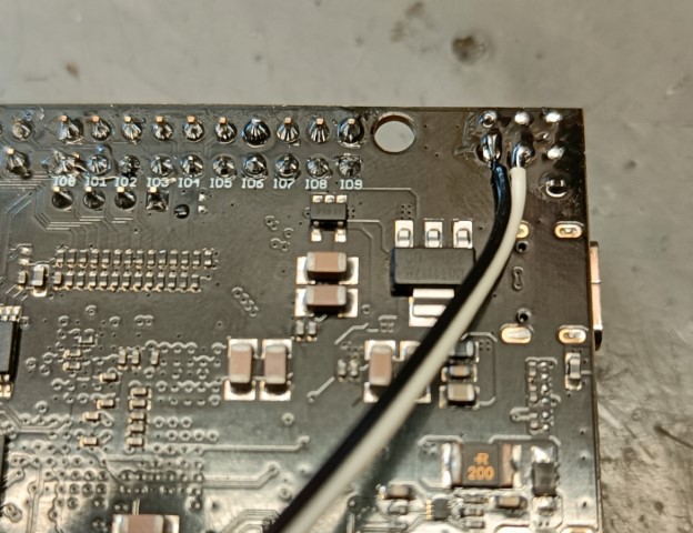
| Certain Buttons do not work | Check continuity between Arduino and CPU pins. Right click image, open in new tab for higher resolution.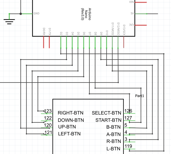
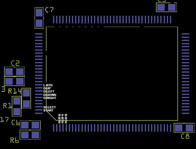
|
Step 18
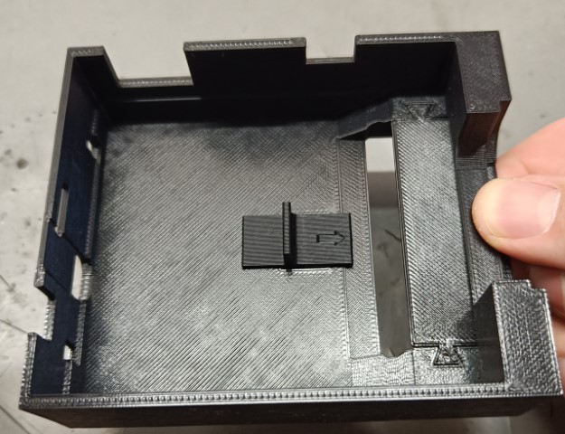
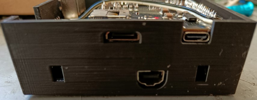
Time to assemble the unit. Make sure the small alignment part is added first and set up the shell as shown in the image. Hold the shell as shown with 1 hand when inserting the pcb sandwich. The nice side of the flat 3D part has to look downwards in this picture.
Step 19
Slowly slide in the whole pcb sandwich until all ports align. This is a very tight fit.
Step 20
Add the U piece and close everything up with the pressfit lid.
Additional Information
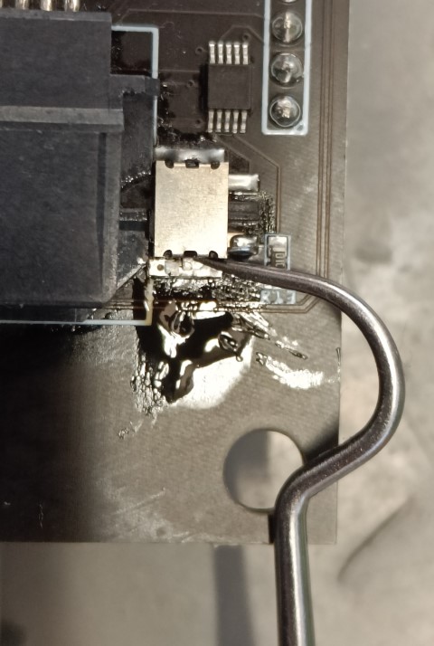
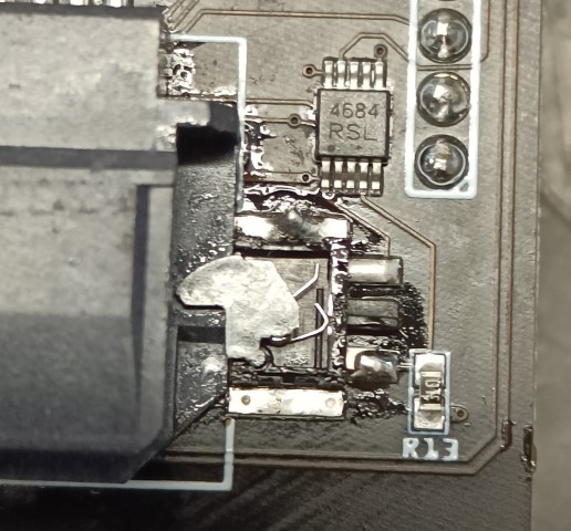
How to trim the Microswitch
Remove solder from one side with some wick, lift the fin of the shield while applying heat. Be careful when soldering that you do not solder the micro10 chip. Then heat the other side and carefully remove the shield. Cut the shield as seen in the image and carefully solder it back on.